
English


A Flexible Printed Circuit Board is more than a rigid board made thin. It uses flexible dielectric materials, usually polyimide, to route signals through tight spaces or moving assemblies. That design can reduce connectors, lower weight, and help products fit compact shapes. The benefits are real. So are the trade-offs.
Joe Fjelstad, a recognized flexible-circuit technology expert and author of Flexible Circuit Technology, has emphasized that flex circuits need to be designed around their materials, bend behavior, and assembly process. A concise paraphrase of his guidance is: “Design for the real bend, not an idealized one.” That principle matters in practice. A circuit folded once during installation faces different stresses from one that moves repeatedly in service. Copper type, layer stack-up, bend radius, and stiffener placement all affect reliability.
Why choose a Flexible Printed Circuit Board? The answer depends on the product. In a compact camera module, a flexible circuit can connect components across a hinge without bulky wiring. In a wearable device, it can follow a curved enclosure while keeping connections organized. But flex is not automatically cheaper or more durable. Poorly planned bends can cause cracking, and specialized fabrication may raise cost. Engineers should review the motion, environment, assembly sequence, and test plan before choosing a construction. A prototype helps expose assumptions. It may also show that a rigid-flex design—or a conventional rigid board—is the better fit.
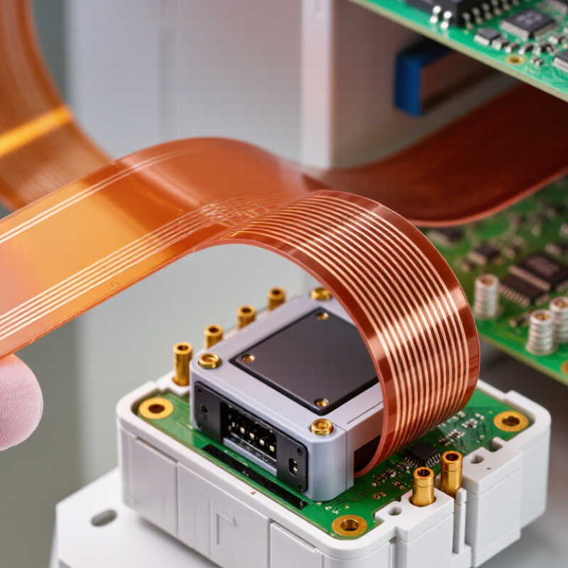
A flexible printed circuit board (FPCB) is an electrical circuit built on a bendable insulating film, commonly polyimide. Copper traces are patterned onto the film and protected by a coverlay; components can also be mounted directly on selected areas. Unlike a rigid board, an FPCB can pass through a narrow hinge or follow a curved housing. Picture a phone camera module or a wearable strap. It is not simply a thinner PCB.
A 2024 market report by Fortune Business Insights valued the global FPCB market at USD 19.10 billion in 2023. It forecast growth to USD 34.74 billion by 2032. That estimate reflects demand across electronics, automotive systems, and medical devices. Still, a market forecast is not a design recommendation. Bend radius, copper type, layer count, and flex cycles affect reliability. A board that bends once during assembly may need different construction from one that moves thousands of times.
Tips: Mark static-bend and dynamic-flex zones, then test the actual routing with connectors installed. Leave room for strain relief. Small details matter near a stiffener edge, where copper can crack.
| Dimension | Flexible Printed Circuit Board (FPC) | Why It Matters |
|---|---|---|
| Definition | A circuit built on a thin, flexible insulating film, with conductive traces that connect electronic components. | It can route electrical connections through compact or non-flat spaces where a rigid board may not fit easily. |
| Common Base Material | Polyimide is widely used; other film materials may be selected for specific electrical, thermal, or cost requirements. | Material choice affects flexibility, heat resistance, insulation, and manufacturing suitability. |
| Shape and Packaging | Can be designed to fold, bend, or follow a curved product surface, subject to the design’s mechanical limits. | May reduce connector count and help use available space more efficiently. |
| Bending and Flex Life | Static bends and repeated-motion applications require different designs. Bend radius and cycle life depend on materials, copper layout, stack-up, and assembly. | Specify the bend conditions early; repeated flexing can cause fatigue if the circuit is not designed for it. |
| Weight and Profile | Often thinner and lighter than an equivalent rigid-board assembly, although the result depends on layer count and reinforcement. | Can support lightweight, low-profile product designs. |
| Electrical Design | Supports single- or multilayer circuits; trace geometry and material properties must be designed for the required electrical performance. | Signal integrity, current capacity, and impedance requirements should be considered alongside mechanical flexibility. |
| Typical Applications | Used in applications such as cameras, displays, medical equipment, automotive electronics, and compact consumer devices. | Useful when electronics must connect across moving, curved, or space-constrained areas. |
| Design Considerations | Requires attention to bend zones, copper placement, stiffeners, coverlay, assembly support, and handling. | Early coordination between electrical, mechanical, and manufacturing design helps reduce reliability and assembly risks. |


QUICK LINKS
CONTACT US
Office: (+86) 755 23040566
Tel: (+86) 158 9965 5195
E-mail: sale@pcbledmodule.com
Skype: Hans@Rocket-PCB
Whatsapp: 86 1589965 5195
Office Address: 2207,Bid 4,He Gu Shan Hui Cheng,35#,Guang Tian RoYanluo street, Song Gang Town,518105 SHENZHENG, CHINA
Plant ADD.: No 69, Lianfeng North Road, Xianxi Area, ChangAn Town, Dongguan, China.


Copyright © 2025 Rocket PCB Solution Ltd. | All Rights Reserved Sitemap Friendship link: CNC machining heat sink