What Is a Rigid Flex Board and How Does It Work?
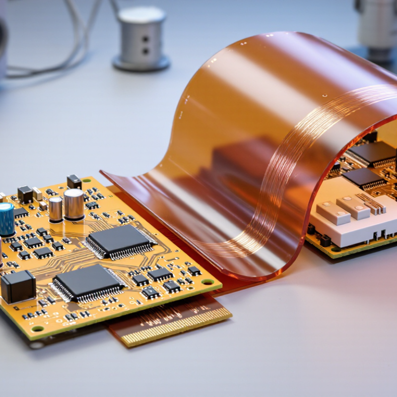
A Rigid Flex Board combines rigid circuit sections with flexible layers in one engineered assembly. It can fold, bend, and connect components within tight spaces. Unlike separate boards joined by cables, this structure reduces connectors and potential failure points. It also saves space inside products such as cameras, medical instruments, industrial sensors, and aerospace equipment.
The board works through carefully stacked copper traces, insulating films, stiffeners, and rigid materials. Flexible areas usually use polyimide, while rigid zones support components and mechanical loading. During operation, electrical signals travel continuously across both sections. The flexible portion moves within its specified bend radius, rather than folding sharply. That detail matters.
In practical manufacturing, layer alignment, copper thickness, adhesive control, and surface finish affect reliability. Engineers inspect the design using impedance calculations, thermal analysis, and bending-cycle tests. Experienced manufacturers also review drilling, plating, soldering, and assembly limits before production. A small design mistake can create cracks near the transition area.
The phrase sounds simple. The engineering is not.
A reliable Rigid Flex Board requires cooperation between electrical designers, mechanical engineers, and fabrication specialists. Its advantages are significant, but they are not automatic. Cost, repairability, material selection, and production yield deserve careful consideration. This guide explains how the structure is built, how it functions, and where design decisions can fail. It also recognizes an important limitation: laboratory performance may differ from long-term field behavior. Testing under realistic temperature, vibration, and movement conditions remains essential.
What Is a Rigid-Flex Board?
What Is a Rigid-Flex Board?
A rigid-flex board combines rigid circuit sections with flexible circuit layers in one interconnected assembly. The rigid areas support components, connectors, and mounting holes. The flexible section bends through a controlled radius, allowing the board to fit inside compact or moving equipment. Copper traces pass continuously between both areas. This removes several cable and connector connections.
Its construction usually includes polyimide flexible layers, copper conductors, coverlay, and rigid laminate sections. Engineers define bend zones before layout begins. A bend zone should not contain sharp corners, heavy components, or unnecessary vias. The minimum bend radius depends on layer count, copper thickness, and whether the board bends once or repeatedly. Smaller is not always better.
In practical design reviews, clearance often causes trouble. A trace may pass safely through a flat area but fail after folding. Fabricators also inspect layer registration, exposed copper, adhesive flow, and plated holes near the transition. Thermal cycling can reveal weaknesses that a visual inspection misses. I have found that early mechanical prototypes expose problems faster than screen-based checks. Still, prototypes do not predict every production variation. Engineers should verify material data, impedance requirements, bend limits, and assembly conditions with the fabricator. A rigid-flex board is not simply a flexible cable attached to a rigid board. It is a coordinated structure that must survive electrical, mechanical, and thermal demands.
How Rigid-Flex Boards Combine Hard and Flexible Sections
What Is a Rigid Flex Board and How Does It Work?
A rigid-flex board joins solid circuit sections with flexible polyimide layers. The rigid areas support components, connectors, and mechanical fastening. The flexible sections bend through a phone hinge, camera module, or compact medical instrument. Copper traces continue across both regions, carrying power and signals without separate cable assemblies. The board folds into three-dimensional spaces. It also reduces connectors, solder joints, and potential failure points. IPC-2223C recommends controlled bend zones, defined layer structures, and suitable copper geometry. A 2024 global market forecast projects the rigid-flex sector to grow above 10% annually through 2030.
Rigid and Flexible Construction
The rigid section usually uses laminated dielectric material and plated through-holes. The flexible section uses thin dielectric films, rolled copper, and carefully shaped traces. Designers avoid placing vias, pads, or sharp copper corners inside repeated bend areas. A broad trace bends more reliably than a narrow, heavily etched one. That detail matters.
Assembly and Reliability Considerations
During assembly, engineers often stiffen the component area with extra laminate or a rigidener. The transition needs gradual support, not an abrupt thickness change. Static bending may occur once during installation, while dynamic bending can happen thousands of times. The real number depends on radius, temperature, copper type, and motion speed. Designers sometimes trust the headline bend radius too much. That assumption can fail in production. The 2024 Electronics Technology Roadmap identifies flex reliability and material durability as continuing design concerns. Prototype testing under actual movement remains essential.
What Materials and Layers Form a Rigid-Flex Board?
A rigid-flex board combines stiff circuit sections with bendable polyimide zones. Its layer structure determines how reliably it carries power, signals, and movement. The rigid areas usually use woven glass-reinforced epoxy laminates. These sections support connectors, components, and mounting hardware. Flexible areas commonly use polyimide film with rolled copper foil. Polyimide tolerates repeated bending better than many rigid materials. It is thin, stable, and resistant to moderate heat. Short traces matter.
Copper forms the conductive paths on both rigid and flexible sections. An insulating dielectric separates copper layers and controls electrical spacing. Adhesive films may bond flexible layers, while prepreg bonds rigid layers during lamination. Coverlay protects exposed flexible copper. Solder mask normally protects rigid copper and defines component pads. Some designs add stiffeners near connectors. A stiffener may use polyimide, fiberglass, or another rigid support material. It prevents damaging bends at fragile termination points.
A typical stackup may include signal copper, dielectric, power copper, and a ground plane. Plated-through holes connect rigid layers, while smaller blind or flexible vias can reduce bending stress. During assembly, heat and pressure cure the bonding materials into one structure. Designers must control copper thickness, bend radius, layer symmetry, and impedance. Otherwise, a board can work electrically but fail mechanically. That lesson is easy to overlook. Material selection also depends on motion cycles, temperature, and space limits. No single stackup fits every product. Prototype testing should measure flex fatigue, peel strength, and dimensional change before production.
What Is a Rigid-Flex Board and How Does It Work?
A rigid-flex PCB combines rigid FR-4 sections with flexible polyimide sections. Copper layers carry electrical signals, while dielectric films, adhesives, coverlays, solder masks, and stiffeners provide insulation, protection, and mechanical support.
Typical material thickness ranges: The values below are representative engineering ranges in millimeters. Actual stack-ups vary according to layer count, bend requirements, current capacity, impedance targets, and mechanical design.
How a Rigid-Flex Board Works in Electronic Devices
A rigid-flex board combines solid circuit sections with flexible polyimide layers. The rigid areas support components, connectors, and heat-producing devices. The flexible section bends through hinges, folds, or narrow internal spaces. It works like a controlled electrical bridge.
Copper traces continue across both structures. During assembly, the board can fold into a three-dimensional shape. This reduces cables, connectors, and separate wiring points. Fewer connections can improve reliability, although poor bending design still causes failures. The bend radius must remain above the manufacturer’s limit. Repeated folding can eventually crack copper layers.
A practical design review checks layer alignment, impedance, thermal paths, and mechanical stress. Engineers may add stiffeners near soldered components. They may also use adhesive layers to support flexible regions. The process is precise, but not perfect. Small registration errors can change signal performance. That detail is easy to underestimate.
MarketsandMarkets’ 2024 Flexible Electronics Market report projects growth from approximately 37.3 billion dollars in 2024 to 64.3 billion dollars by 2029. This trend reflects rising demand for compact, lightweight electronic assemblies. Fortune Business Insights also identifies aerospace, medical equipment, and consumer electronics as major rigid-flex applications in its 2024 market analysis. These figures are forecasts, not guarantees. Real performance still depends on material selection, bend testing, and production control.
Where Rigid-Flex Boards Are Used and Why They Matter
Rigid-flex boards combine solid FR-4 sections with thin, bendable polyimide layers. Plated copper vias connect both zones electrically. The rigid areas hold components, connectors, and heat-producing parts. The flexible section folds through narrow spaces, reducing cables, plugs, and assembly points. In practical design reviews, this structure often saves enclosure space, but bend radius remains easy to underestimate.
Where rigid-flex boards are used matters most.
Medical instruments place them around curved housings and moving sensors. Aerospace systems use them where vibration, weight, and limited volume create constant pressure. Industrial cameras, automotive controls, and compact wearables also benefit from fewer interconnects. MarketsandMarkets reported that the global flexible electronics market could reach about 87.2 billion dollars by 2028, with flexible circuit integration supporting that expansion. Grand View Research also identifies miniaturization and lightweight electronics as major growth drivers. These figures do not guarantee every rigid-flex project will succeed. Material choices, thermal cycling, and repeated bending still decide reliability.
Tips:
Define the bend zone before routing copper. Keep vias and stiffeners outside the folding area. Follow IPC-2223 guidance for bend radius and flex construction. Test the board inside the real enclosure, not only on a flat fixture. A small design mistake can create copper cracks after thousands of cycles. Designers sometimes trust simulation too much. Physical testing remains necessary.