
English


A PCB can look flawless and still fail when power reaches its copper traces. A misplaced component, open connection, or solder bridge may cause intermittent faults that visual inspection cannot reveal. Electrical Testing Pcb checks whether a board’s circuits behave as designed, before those faults reach equipment or customers. The stakes are practical: a multimeter probe, flying-probe tester, or bed-of-nails fixture can expose problems while the board is still on the bench. Small details matter.
Industry guidance helps define what a reliable test should cover. IPC-9252B, Requirements for Electrical Testing of Unpopulated Printed Boards, provides a recognized framework for electrical testing of bare boards; IPC-6012E sets qualification and performance requirements for rigid printed boards. IPC’s 2024 Electronics Industry Economic Outlook offers broader context on the manufacturing pressures facing electronics producers, where quality and delivery expectations make early fault detection valuable. These sources do not replace a board-specific test plan. They help teams choose meaningful checks, such as continuity, isolation, and power-on measurements, while documenting limits and results. A test that only confirms continuity can miss a functional fault. That is easy to overlook. The sections that follow explain how to select a method, prepare the PCB, and interpret results without treating one pass as proof of perfection.
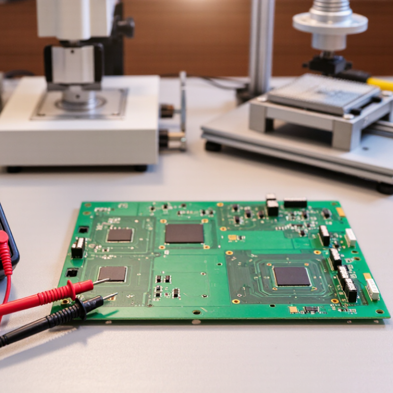
Before testing a PCB for electrical functionality, prepare it for safe inspection. Disconnect the power source, remove batteries, and allow stored charge to dissipate. Use an ESD-safe work surface. Under bright light, inspect both sides for solder bridges, lifted pads, cracked components, or debris. A magnifier helps. Photograph the board before making changes; later, even a small repair can obscure its original condition.
Use the schematic or netlist to locate ground, power rails, and key signal paths. Mark accessible test pads on a printed copy or in a clear photo. Do not rely on silkscreen labels alone; labels can be faint, misplaced, or shared across board revisions. Check that each chosen point matches the intended connection. With power disconnected, use a multimeter’s continuity mode to verify ground points and look for unexpected shorts between supply rails. Keep probe tips steady. A slipped probe can bridge adjacent pads.
Choose points with enough exposed metal for reliable contact, and note the expected voltage or signal before applying power. Some boards have no dedicated test pads, so a connector pin or component lead may be the practical alternative. That choice deserves care. Recheck the schematic and probe placement before powering the board, preferably with a current-limited supply. Preparation can feel fussy, but rushing it makes later readings harder to trust.
QUICK LINKS
CONTACT US
Office: (+86) 755 23040566
Tel: (+86) 158 9965 5195
E-mail: sale@pcbledmodule.com
Skype: Hans@Rocket-PCB
Whatsapp: 86 1589965 5195
Office Address: 2207,Bid 4,He Gu Shan Hui Cheng,35#,Guang Tian RoYanluo street, Song Gang Town,518105 SHENZHENG, CHINA
Plant ADD.: No 69, Lianfeng North Road, Xianxi Area, ChangAn Town, Dongguan, China.


Copyright © 2025 Rocket PCB Solution Ltd. | All Rights Reserved Sitemap Friendship link: CNC machining heat sink