
English


Choosing the right Micro Hydraulic Actuator begins with the real motion, not the product catalogue. A compact cylinder may fit the available space, yet deliver poor control under changing loads. Engineers should examine force, stroke, speed, pressure, duty cycle, mounting position, and fluid compatibility. These details decide whether the actuator performs reliably inside a medical device, robotic gripper, inspection tool, or precision machine.
Hydraulic engineering author John Watton has emphasized a practical design truth: “Good hydraulic design is always a compromise between performance, cost, and reliability.” That principle remains useful when comparing miniature actuators. A unit producing impressive peak force may overheat during repeated cycles. Another may operate smoothly but require a pump that overwhelms the system’s size and energy budget. Small components still need careful seals, clean fluid, accurate valves, and sensible safety margins.
Measure twice.
This guide will explain how to compare Micro Hydraulic Actuator options with greater confidence. It will connect technical specifications to physical results, such as a rod extending without hesitation or holding a load without visible drift. Manufacturer reputation also matters, but it should not replace testing. Request pressure-flow curves, leakage data, endurance results, and mounting drawings. Then challenge the assumptions behind them.
No selection chart is perfect. Real installations contain vibration, temperature changes, imperfect alignment, and occasional maintenance gaps. A thoughtful choice accepts those weaknesses instead of hiding them. The best actuator is not always the smallest or strongest model. It is the one that delivers controlled motion, dependable service, and manageable integration within the complete hydraulic system.
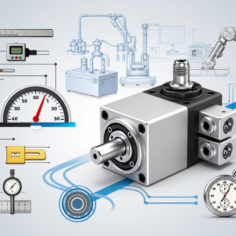
How to Choose the Right Micro Hydraulic Actuator?
Selecting a micro hydraulic actuator begins with four measurable requirements: force, stroke, speed, and duty cycle. Force should include the working load, friction, and a safety margin. For vertical movement, include the load’s full weight. A small error here can cause stalling or excessive pressure.
Stroke means the actuator’s actual movement distance, not the available space around it. Measure the complete mechanical travel, including end clearances. Speed should describe movement under real load conditions. An actuator may reach its rated speed without a load, but move much slower during operation. I once underestimated acceleration time in a compact mechanism. The design worked on paper, but felt sluggish in testing. That mistake was useful, though avoidable.
Duty cycle defines how long the actuator runs and how often it repeats. A unit moving for two seconds every minute has a different thermal demand from one operating continuously. Check oil temperature, pressure losses, cooling, and repeated starts. Small housings can heat quickly. Sometimes, intermittent operation is safer than maximum speed.
Tips:
Record force and speed during prototype testing, not only from calculations. Add a pressure sensor if possible. Confirm the required stroke with a physical mock-up. Leave room for alignment errors and seal wear. If the actuator runs hot, reduce frequency or speed before increasing capacity. Recheck the duty cycle after the mechanism changes. Tiny design changes matter.
| Selection Parameter | What It Means | Practical Micro-Actuator Range | How to Define the Requirement |
|---|---|---|---|
| Required Force | The linear push or pull force needed at the actuator rod or piston. | Approximately 10 N to 5,000 N for compact hydraulic applications. | Calculate the external load, friction, acceleration force, and any gravity component. Add a safety factor of about 1.25 to 1.50: Design Force = Calculated Load × Safety Factor. |
| Pressure | Hydraulic pressure available to generate actuator force. | Common compact-system values are approximately 70 to 250 bar, depending on construction and application. | Confirm that the actuator rating is equal to or higher than the maximum system pressure. Continuous operating pressure should not be treated as the same as short-duration peak pressure. |
| Piston Area | The effective hydraulic area on which pressure acts. | Typical bore diameters may range from about 6 mm to 25 mm in micro-cylinder designs. | Estimate theoretical extension force with F = P × A, where F is force in newtons, P is pressure in pascals, and A is piston area in square metres. Account for seal friction and mechanical losses. |
| Rod Diameter | The diameter of the actuator rod, which affects buckling strength, retraction force, and stiffness. | Often approximately 3 mm to 16 mm for compact actuators. | Select a rod large enough for compressive loading and side-load resistance. Retraction force is lower than extension force because the rod area reduces the effective return-side piston area. |
| Stroke Length | The maximum linear travel available from the fully retracted to the fully extended position. | Approximately 5 mm to 150 mm for many micro hydraulic applications. | Specify the actual required travel and include clearance at both end positions. Avoid using the mechanical end stop as the normal operating position. |
| Position Accuracy | How closely the actuator can reach and hold the commanded position. | Basic open-loop systems may provide millimetre-level positioning; feedback-controlled systems can achieve substantially finer repeatability under controlled conditions. | Define accuracy, repeatability, and resolution separately. If the load varies or the actuator must hold an intermediate position, consider a position sensor and a proportional or servo valve. |
| Operating Speed | The rate at which the piston or rod extends or retracts. | Approximately 1 to 300 mm/s, depending on flow rate, load, bore size, pressure, and valve configuration. | Use v = Q ÷ A, where v is speed, Q is flow rate, and A is effective piston area. Check both loaded and unloaded speeds, because actuator speed changes with load and available flow. |
| Flow Requirement | The hydraulic flow needed to achieve the specified speed. | Often approximately 0.05 to 5 L/min for compact hydraulic cylinders. | Estimate flow from Q = A × v, then add allowance for leakage, valve losses, temperature effects, and pump variation. Ensure the valve and tubing can deliver the required flow without excessive pressure drop. |
| Duty Cycle | The operating pattern, including run time, idle time, cycle frequency, and load profile. | Intermittent duty may be a few cycles per minute; continuous-duty designs require suitable cooling and component ratings. | State the number of cycles per hour, extension time, retraction time, dwell time, load during each movement, and standby pressure. Use the worst-case thermal condition for sizing. |
| Cycle Time | The total time required for one complete operating sequence. | Common compact-machine cycle times range from less than one second to several minutes. | Calculate extension time as Stroke ÷ Extension Speed and retraction time as Stroke ÷ Retraction Speed. Add dwell, valve response, and control-system delays. |
| Load Direction | Whether the actuator is pushing, pulling, lifting, lowering, or resisting an external force. | Push and pull loads should be specified separately because effective piston areas differ. | For lifting or lowering applications, include gravity, possible shock loading, and the risk of uncontrolled movement. A counterbalance, pilot-operated check valve, or mechanical lock may be required. |
| Side Load | A load acting perpendicular to the actuator axis. | Ideally near zero; external guides should carry most transverse loads. | Do not use the actuator rod as a structural guide. Use clevises, spherical joints, or external linear guides where alignment changes or side forces are present. |
| Mounting Arrangement | The method used to attach the actuator to the machine. | Common options include threaded bodies, front or rear pivots, clevis mounts, trunnions, and flange mounts. | Select a mounting style that permits correct alignment throughout the full stroke. Check mounting strength, available installation space, joint articulation, and access for maintenance. |
| Installation Envelope | The total space occupied by the actuator and its connections during operation. | Compact body diameters may be approximately 10 to 35 mm, with overall lengths determined by stroke and mounting design. | Check retracted length, extended length, port orientation, hose bend radius, connector clearance, and the space required for service or replacement. |
| Fluid Compatibility | The suitability of the hydraulic fluid for seals, cylinder materials, valves, and hoses. | Mineral hydraulic oils are common; water-based or biodegradable fluids require specifically compatible materials. | Specify fluid type, viscosity range, temperature range, cleanliness level, and seal material. Never assume that a seal compatible with mineral oil is suitable for water-based fluid. |
| Operating Temperature | The temperature range of the hydraulic fluid and surrounding environment. | A general design range may be approximately -20°C to 80°C, subject to seal, fluid, and material limitations. | Rate the actuator for the actual minimum and maximum temperatures. High temperature lowers fluid viscosity and can accelerate seal wear; low temperature increases viscosity and slows response. |
| Leakage Control | The ability of the actuator and circuit to limit internal and external hydraulic leakage. | Leakage performance depends on seal design, pressure, temperature, surface finish, contamination, and service life. | Define whether minor internal leakage is acceptable. For long-duration load holding, use an appropriate load-holding valve or mechanical locking method instead of relying only on the actuator seals. |
| Environmental Protection | Resistance to dust, moisture, chemicals, vibration, and corrosion. | Protection levels vary from indoor clean environments to sealed outdoor or washdown applications. | Identify exposure to water, dust, salt spray, chemicals, impact, and vibration. Specify suitable rod coatings, wipers, corrosion-resistant materials, and enclosure protection for the installation. |
| Safety Factor | The margin between the expected operating requirement and the actuator's rated capability. | A factor of approximately 1.25 to 1.50 is commonly used for predictable static loads; higher margins may be needed for shock or uncertain loads. | Apply the safety factor to force, pressure, speed, and structural loads as appropriate. Do not exceed the manufacturer's maximum pressure, buckling, or side-load limits. |
QUICK LINKS
CONTACT US
Office: (+86) 755 23040566
Tel: (+86) 158 9965 5195
E-mail: sale@pcbledmodule.com
Skype: Hans@Rocket-PCB
Whatsapp: 86 1589965 5195
Office Address: 2207,Bid 4,He Gu Shan Hui Cheng,35#,Guang Tian RoYanluo street, Song Gang Town,518105 SHENZHENG, CHINA
Plant ADD.: No 69, Lianfeng North Road, Xianxi Area, ChangAn Town, Dongguan, China.


Copyright © 2025 Rocket PCB Solution Ltd. | All Rights Reserved Sitemap Friendship link: CNC machining heat sink