How to Choose the Best FOC Motor Controller?
Choosing a Foc Motor Controller is not just a matter of matching voltage and current ratings. The controller shapes torque response, speed stability, heat, and efficiency. In a small electric vehicle, for example, a poorly tuned drive may feel jerky when starting uphill. The right choice depends on the motor, load, supply, cooling, and control needs.
The market context is significant. The International Energy Agency’s Global EV Outlook 2024 reports nearly 14 million electric-car sales in 2023, about 18% of global car sales. That growth makes reliable motor control increasingly important, though it does not prove that one controller design suits every application. Small details matter. Motor-drive researcher R. Krishnan’s published work on electric drives supports a practical takeaway: choose the control method to fit the motor and its operating range. This is a paraphrase, not a direct quotation. Compare continuous and peak current, sensor options, low-speed performance, thermal limits, tuning tools, and protection features. Check whether the controller’s specifications were tested under conditions resembling your real load. A neat datasheet can still leave unanswered questions. I would not treat “FOC” as a guarantee of smooth operation; wiring, parameter settings, and cooling can change the result. The sections ahead explain how to assess these factors and select a Foc Motor Controller with evidence, not labels alone.
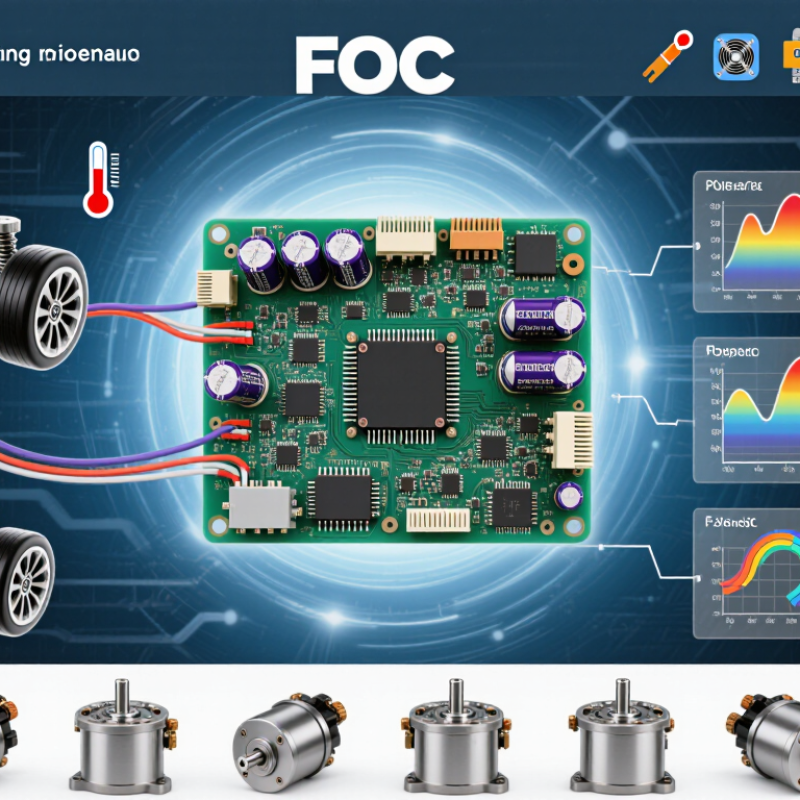
Define the Application and Motor Requirements
Define the application before comparing controller features. A pump, mobile robot, and precision spindle place very different demands on a motor. Record the required speed range, shaft torque, acceleration time, and operating hours. Start with the load. Note whether it changes suddenly, such as a conveyor starting with a full belt. Measure, do not guess. Estimate peak and continuous current from the motor data and real operating conditions. A controller sized only for average demand may overheat during repeated starts. Also check the supply voltage and whether the system can handle regenerative energy during deceleration.
Identify the motor type and its electrical limits, including phase current, rated speed, and pole pairs where available. Confirm that the controller supports the motor’s feedback method, such as Hall sensors, an encoder, or sensorless operation. These details affect startup behavior and low-speed control. Check the installation environment, too: a sealed enclosure near a warm motor has less cooling than an open test bench. Leave practical margin for temperature and load variation, but avoid oversizing without reason. It can add cost and make current settings harder to tune. Real installations are rarely perfect. Document the duty cycle and the worst credible load; those notes make controller comparisons more meaningful.
Match Controller Ratings to Voltage, Current, and Motor Type
Match the controller’s voltage range to the battery across its full operating cycle, not just its label. A nominal 48-volt pack may reach 54.6 volts when fully charged, while regenerative braking can raise the DC bus further. Leave headroom below the controller’s maximum voltage, and check that its undervoltage limit suits battery sag under load. Small margins matter. The U.S. Department of Energy’s 2014 Improving Motor and Drive System Performance sourcebook reports that motor-driven systems account for about 68% of U.S. manufacturing electricity use. That figure shows why drive selection deserves care; it does not promise any particular energy saving.
Check continuous phase current and peak current separately. A peak rating may last only seconds, and cooling conditions can change the continuous rating. Compare the controller’s phase-current rating with the motor’s limits, then confirm whether its advertised battery-current rating means something different. A spec sheet can be confusing here. It is easy to over-trust one large number.
Finally, verify motor compatibility. FOC controllers commonly support permanent-magnet synchronous or brushless motors, but sensor requirements vary. Check whether your motor uses Hall sensors, an encoder, or sensorless operation, and confirm the controller supports that feedback method. For a loaded motor, startup torque and low-speed control matter as much as top speed. I would still allow some margin; real wiring, heat, and installation rarely match a perfect test bench.
Compare FOC Features, Sensors, and Configuration Options
Choosing a field-oriented control (FOC) motor controller means comparing more than peak current and voltage. Check whether its control loop supports your motor’s speed range, load changes, and thermal limits. The International Energy Agency’s 2011 report, Energy-Efficiency Policy Opportunities for Electric Motor-Driven Systems, estimated that motor-driven systems use about 45% of global electricity. Efficiency matters, but a controller’s real performance depends on the motor, tuning, and application. Small details matter. Look for clear current ratings, fault handling, and documented limits—not just an impressive headline number.
Sensor options shape startup, low-speed torque, and wiring complexity. Encoders provide rotor-position feedback; Hall sensors can simplify commutation feedback, while sensorless estimation may reduce wiring but struggle at very low speeds. Match the option to the actual load. A fan and a loaded conveyor do not behave alike. Configuration tools should expose practical settings, including pole pairs, current limits, ramp rates, and protection thresholds. Confirm that settings can be tested safely and restored after a fault. I would still question a tidy spec-sheet comparison: real motor noise, heat, and vibration can reveal problems the table misses. Test under representative conditions, and record what changes. The process is not always neat.
Assess Thermal Performance, Protection, and Connectivity
Thermal performance is more than a peak-current number. Check continuous current at the expected ambient temperature, then inspect the derating curve. A controller rated for 40°C may deliver less current inside a sealed cabinet at 55°C. Measure the case temperature during repeated acceleration and braking, not only at idle. Heat matters. The IEA’s 2011 report, Energy-Efficiency Policy Opportunities for Electric Motor-Driven Systems, estimates motor-driven systems use 43–46% of global electricity. That scale makes efficient operation important, but efficiency figures alone cannot reveal whether a controller will overheat in your installation.
Protection features should match the motor and load. Look for configurable overcurrent, overtemperature, undervoltage, and stall protection. Confirm how the controller reports faults and whether it recovers automatically; unexpected restarts can surprise operators. The U.S. Department of Energy’s 2014 Improving Motor and Drive System Performance sourcebook reports that motor-driven systems use about 68% of U.S. manufacturing electricity. System conditions matter. Connectivity helps make them visible: CAN, RS-485, or Ethernet interfaces can expose current, temperature, speed, and fault history to a supervisory system. Check update rates, available diagnostic detail, and behavior after communication loss. A live dashboard is useful, but logged data is often more revealing. I would still test the actual cable length and electrical noise in the machine; specifications rarely capture every installation quirk.
Validate Controller Performance in the Target System
A controller that looks efficient on a bench may behave differently inside the target machine. Test it with the intended motor, supply voltage, load, and cooling arrangement. Mount the motor as it will be used, including its real cables and mechanical coupling. Small details matter. A long cable run or restricted airflow can change noise, temperature, and current readings.
Measure phase current, bus voltage, speed, and controller temperature during startup, steady operation, and rapid load changes. Use suitable probes and keep measurement wiring short to reduce misleading noise. Check low-speed torque, acceleration, deceleration, and operation near the expected speed limit. Watch the heat. A brief run can hide thermal problems, so repeat demanding cycles until temperatures stabilize. Compare measured current and speed with the controller’s feedback data; disagreement may point to sensor setup or scaling errors.
Test the actual operating sequence, not just an idealized profile. Include realistic pauses, load spikes, and the lowest expected supply voltage. Log faults and confirm that protective limits respond as intended. A test may reveal that the chosen limits are too cautious—or not cautious enough. That is useful, even if it means revisiting an earlier assumption. Bench results still cannot represent every installation, so leave margin for variations in mounting, wiring, and ambient temperature.