

Choosing the right Aluminium Tri-Fold Blind Rivets For Composite Materials can determine whether a joint remains secure under vibration, moisture, and repeated loading. These fasteners are often selected for their wide backside expansion, light weight, and ability to distribute pressure across fragile composite panels. However, performance depends on more than rivet material. Hole diameter, grip range, panel thickness, installation force, and surface condition all matter.
Small details matter.
In workshop testing, a poorly matched rivet may spin, crush the laminate, or leave an uneven head. A correctly installed rivet usually produces a broad, stable clamping area with minimal surface distortion. This article presents seven practical tips for selecting and installing these blind rivets. It discusses measuring the joint accurately, checking compatibility between aluminium and composite skins, preparing clean holes, and using suitable installation tools. It also considers corrosion risk, sealing requirements, and inspection after fastening. These recommendations reflect common engineering practice, but they should not replace supplier data or project-specific testing. Composite structures vary widely, and a method that works on a thin glass-fiber panel may fail on a carbon-fiber assembly. That limitation deserves attention. Reliable results come from combining hands-on observation with technical documentation, controlled trials, and clear quality checks. Before production use, confirm the rivet’s load capacity, grip specification, and installation requirements with the manufacturer. A secure joint begins with careful judgment, not assumptions.
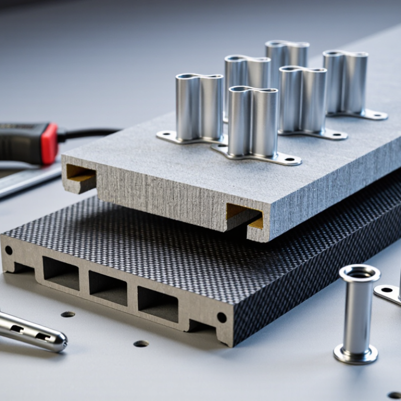
Aluminium tri-fold blind rivets suit composite panels where rear access is limited. Their three legs open behind the panel and create a broad bearing area. This can reduce local crushing around the hole. A 2024 MarketsandMarkets report valued the global composites market at roughly USD 95 billion, increasing demand for lighter fastening systems. Yet composites are not simply thin metal sheets.
Tip: check the rivet’s grip range carefully. A short rivet may not form fully. An overly long rivet can leave loose legs behind the panel. Drill cleanly, using a sharp bit and light pressure. Support the laminate to limit splintering. Seal the hole when moisture exposure is expected.
Aluminium offers low mass and useful corrosion resistance. The U.S. Department of Energy reports recycled aluminium uses about 5% of the energy required for primary production. That supports material efficiency, but fastener selection still needs testing.
Aluminium against carbon-fibre composites may create galvanic corrosion when moisture bridges both materials. Add an insulating washer, coating, or compatible sealant where appropriate. I have found visual inspection alone unreliable.
Pull-through testing on the actual laminate is safer. An imperfect fit can look acceptable, then loosen after vibration, heat, or repeated loading. Record hole diameter, clamp force, installation torque, and failure mode during trials.
1) Measure the drilled hole.
2) Match the rivet diameter closely. A loose hole can reduce clamping and increase laminate crushing.
The ASM Handbook lists aluminium density near 2.70 g/cm³, compared with about 7.85 g/cm³ for steel, but lower weight does not mean lower design risk.
3) Select the grip range after measuring the total stack, including washers, coating, and uneven surfaces. The rivet should work near the middle of its grip range. Short grip causes poor forming. Excess grip can leave an unstable tail.
4) Choose the alloy for strength and corrosion resistance. A corrosion-resistant aluminium body may suit glass-fibre laminates, while carbon-fibre laminates require electrical isolation.
5) Check the mandrel material and head geometry.
6) Review the manufacturer’s load tables, then verify them with representative laminate coupons. ISO 14589 specifies tensile and shear testing for blind rivets, while ASTM D5961/D5961M addresses bearing response in polymer-matrix composites. These tests matter because laminate orientation changes failure loads.
7) Inspect spacing and edge distance. FAA AC 43.13-1B uses roughly 2D as a conventional minimum edge distance for many metal joints, but composites may need more. Do not copy that figure blindly. A neat drawing can still fail.
My practical mistake would be trusting nominal thickness instead of measuring the real stack; adhesive squeeze-out often changes it. Pull a sample rivet, inspect the formed tail, and record the result before production.
7 Tips for Aluminium Tri Fold Blind Rivets for Composites
Check the laminate first: fiber type, resin system, thickness, moisture, and service temperature. Check galvanic compatibility, especially with carbon-fiber laminates. Aluminium can corrode when conductive fibers, moisture, and oxygen share the joint. A nonconductive coating or isolating washer may help, but verify chemical compatibility. Check the rivet’s tri-fold footprint behind the panel. The legs should spread evenly without crushing the laminate or creating sharp local bends. Small details matter.
Check hole diameter and quality against the rivet supplier’s controlled installation range. Composite holes should be drilled with sharp tooling, backed properly, and inspected for delamination. Check edge distance before drilling. FAA AC 43.13-1B commonly uses 2D as a minimum rivet edge-distance starting point, where D is rivet diameter; composite allowables still require validation. Check pitch and joint width for bearing, bypass, and pull-through loads. CMH-17-3G identifies these as critical composite joint failure modes. ASTM D5961 provides a recognized method for bearing-response testing.
Check installation force and backside deformation on production coupons. Record temperature, cure condition, hole size, and failure mode. Check inspection access, because a hidden folded leg can look acceptable while carrying little load. This is where designs often become overconfident. A neat surface is not proof of a reliable joint. Test representative laminates rather than trusting metal-sheet experience alone. Jiova
| Tip | Design Dimension | Practical Requirement or Check | Why It Matters for Composites |
|---|---|---|---|
| 1 | Check laminate and rivet compatibility | Confirm the composite fiber, resin system, laminate thickness, temperature range, moisture exposure, and chemical environment. Aluminium rivets should not be selected solely by nominal diameter. | Carbon-fiber composites can create a galvanic couple with aluminium in the presence of an electrolyte. Glass-fiber composites generally present lower galvanic risk, but the resin, fillers, coatings, and absorbed moisture still affect durability. |
| 2 | Control galvanic corrosion | For carbon-fiber laminates, use an electrically insulating barrier such as a qualified coating, sealant, isolating washer, or nonconductive sleeve where permitted by the assembly design. Seal the hole and faying surfaces against moisture. | Electrical isolation reduces the likelihood of galvanic attack at the aluminium fastener, exposed carbon fibers, and surrounding laminate. The complete protection system must be validated for the service environment. |
| 3 | Match the rivet grip range to the joint stack | Measure the actual compressed joint thickness, including coatings, sealants, washers, and local reinforcements. Select a tri-fold rivet whose specified grip range fully covers the measured stack without relying on excessive deformation. | Tri-fold expansion is sensitive to grip length. An undersized grip can leave the joint loose, while an oversized grip can produce poor folding, excessive compression, or damage to the laminate. |
| 4 | Design the hole correctly | Use the fastener supplier's recommended hole diameter and tolerance. Drill or ream with a sharp, suitable tool; remove burrs; inspect for delamination, fiber breakout, resin cracking, and oversized holes. | Composite holes do not redistribute local stresses as readily as ductile metal. Poor hole quality can reduce bearing strength, initiate delamination, and prevent consistent rivet formation. |
| 5 | Verify edge distance and fastener spacing | Establish edge distance and pitch from laminate allowables, rivet diameter, expected load, and failure-mode analysis. As an initial layout guide, many composite joint designs begin around 3D edge distance and 4D pitch, where D is the hole or rivet diameter, then verify by testing or approved design data. | Insufficient edge distance can cause shear-out or splitting; insufficient pitch can produce net-section failure or excessive interaction between neighboring fasteners. The 3D and 4D values are starting guidelines, not universal acceptance criteria. |
| 6 | Limit clamp-up and bearing damage | Use the approved installation tool, nosepiece, and pull stroke. Confirm that the folded rivet body provides firm contact without crushing the laminate, distorting the face sheet, or creating a visible sink mark. | Composite laminates can be sensitive to concentrated compression. Excessive setting force may cause local crushing or delamination, while insufficient clamp-up may allow fretting and joint movement. |
| 7 | Validate the complete joint in its service environment | Test representative coupons or assemblies for tensile pull-out, lap-shear, bearing, vibration, temperature cycling, humidity, fluid exposure, and electrical isolation when applicable. Inspect the formed rivet and laminate after testing. | Rivet performance depends on the interaction of fastener geometry, laminate lay-up, hole quality, joint thickness, installation method, and environment. A nominal catalogue strength should not replace application-specific validation. |
7 Tips for Aluminium Tri Fold Blind Rivets for Composites
Preparing holes correctly protects both the composite panel and the rivet’s folding legs. Mark each hole carefully, then support the panel from behind before drilling. Use a sharp bit suited to composite materials, and keep pressure light. Excessive force can splinter the laminate or create a crushed entry point. Drill to the diameter specified for the rivet. Do not enlarge the hole by twisting the bit.
Tip 1: Clamp thin panels between smooth backing sheets.
Remove loose fibres with a light countersink or fine abrasive. Avoid aggressive deburring, because it can weaken the laminate around the hole. Clean dust with a lint-free cloth. I still inspect every hole with a small probe, even when the surface looks clean. A hidden delamination can reduce holding strength. For carbon-based composites, use a suitable barrier or sealant where aluminium contact may cause corrosion concerns.
Tip 2: Check the rivet’s grip range before loading the tool.
Place the rivet squarely against the surface, then operate the tool in a controlled motion. The tri fold legs should open behind the panel without crushing it. Stop if the head tilts, spins, or leaves a deep mark. That usually signals poor alignment, an oversized hole, or an unsuitable grip length. Do not force it.
Tip 3: Test one rivet on a scrap panel first.
This small check reveals unexpected panel compression and tool settings. In practice, I sometimes find the first trial looks acceptable but feels too loose after inspection. Rechecking the joint under gentle hand pressure is worth the extra minute.
The chart compares common nominal rivet diameters with their calculated cylindrical shank cross-sectional area. Larger diameters require more careful hole preparation because excessive drilling force, heat, or oversize holes can damage composite laminates.
Areas are calculated using A = πd²/4, where d is the nominal rivet diameter in millimetres. Use the fastener specification for the final drill size, keep the drill perpendicular to the laminate, support the exit surface, and install the rivet with controlled tool pressure.
Inspecting rivet performance starts before installation. The FAA’s AC 43.13-1B commonly references two rivet diameters for edge distance and four diameters for pitch. Treat these as repair baselines, not universal composite rules. Measure the laminate thickness, hole diameter, and rivet grip range. A short grip may leave weak expansion. An excessive grip can crush the laminate. Keep holes clean and round. Avoid forcing a misaligned rivet.
Watch the surface during setting. The tri-fold legs should open evenly against the back face. Check for lifting, resin cracks, whitening, and local delamination. A thin washer can distribute pressure, but only after testing. ASTM D5961/D5961M evaluates bearing response in polymer-matrix composites, reminding engineers that fastener loads need material-specific evidence. Record pull-out loads from representative coupons, not just installation feel. Pull slowly. Note the first visible damage.
Control galvanic risk between aluminium and carbon reinforcement. Use a qualified barrier layer or sealant, then inspect its continuity around the hole. CMH-17 guidance supports statistically based laminate allowables, yet field assemblies rarely behave perfectly. I have seen apparently sound rivets loosen after moisture cycling. That failure was missed during visual inspection. Add borescope checks where access permits. Recheck critical joints after vibration exposure. Also verify mandrel retention, because a missing mandrel can expose a small path for water and corrosion.
QUICK LINKS
CONTACT US
Office: (+86) 755 23040566
Tel: (+86) 158 9965 5195
E-mail: sale@pcbledmodule.com
Skype: Hans@Rocket-PCB
Whatsapp: 86 1589965 5195
Office Address: 2207,Bid 4,He Gu Shan Hui Cheng,35#,Guang Tian RoYanluo street, Song Gang Town,518105 SHENZHENG, CHINA
Plant ADD.: No 69, Lianfeng North Road, Xianxi Area, ChangAn Town, Dongguan, China.


Copyright © 2025 Rocket PCB Solution Ltd. | All Rights Reserved Sitemap Friendship link: CNC machining heat sink